Anyone that has worked with shadowmap shadows will have experienced one of the many types of artifacts associated with this technque, most common of which being the dreaded ‘shadow acne’ or self-shadowing artifacts. I recently found myslef writing shadowing code from scratch, which forced me to revisit some of these issues and make some notes on them. Perhaps some of this will become obsolete once raytraced shadows become the norm, but even then some of these notes will be useful.
I’m making this post mainly a reference to future me, but hopefully it will be useful to other people too! There is nothing groundbreaking here, just a close look into shadowmapping, floating pont conversions and shadow bias.
Shadows from Front or Back faces?
I’ve generally avoided self-shadowing artifacts by rendering back faces (w.r.t. the light) into the shadowmap which pushes any artifacts on the dark side of the object (though there are other issues). This time however I was dealing with geometry that I didn’t have any control over. I was rendering models from the (excellent) Miverva kit and some of the objects there had an exterior skin that was very close to the interior (ceiling).

A simplified representation of this looks like this:
I’ve made the shadow texels extra chunky to illustrate the issue. As you can see the ‘ceiling’ geometry (inner skin) is very close to the ‘roof’ geometry (outer skin) so even though we’re rendering the back faces to the shadowmap, the texels protrude onto the exterior causing self shadowing artifacts.
Had the geometry been a simple convex shape this wouldn’t be an issue.

The artifacts would appear on the back faces of the object, but since those are facing away from the light they would be dark anyway (assuming this is an opaque object).
So effectively, the thin geometry makes this behave as if we were casting shadows from the front faces, so now we have to deal with all the usual biasing issues.
(as a side note, casting shadows from the back faces is not a perfect solution. They come with their own artifacts, but that’s another topic)
A closer look at the issue
Let’s simplify the problem down to a basic setup. A directional light, angled down by 45° and aligned to the X axis. The geometry is just a squashed box, made really thin in the Y axis. All attempts to fix self-shadowing have been removed and the shadowmap resolution has been intentionally made very low.
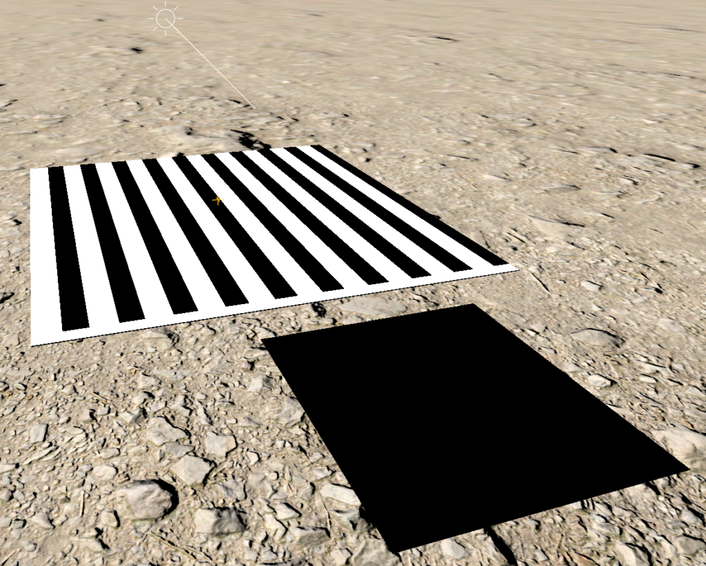
Debug display modes are very useful and most engines have a few of them built in. One that I always chose to implement is to overlay a checkerboard pattern where each square is a shadow texel. It’s a very useful way of visualizing shadow quality and also for diagnosing shadow artifacts.

From this we can see that the texels are indeed quite chunky and that the self shadowing artifacts are half way through the texel. That makes sense and matches the 2D diagram from earlier on.
While that’s useful, I find that adding another debug display mode to show the texels are 3D geometry is more intuitive. We can do this by creating a large mesh of quads and sampling the shadowmap depth in the vertex shader to push each vertex along the light direction. This is what that looks like:
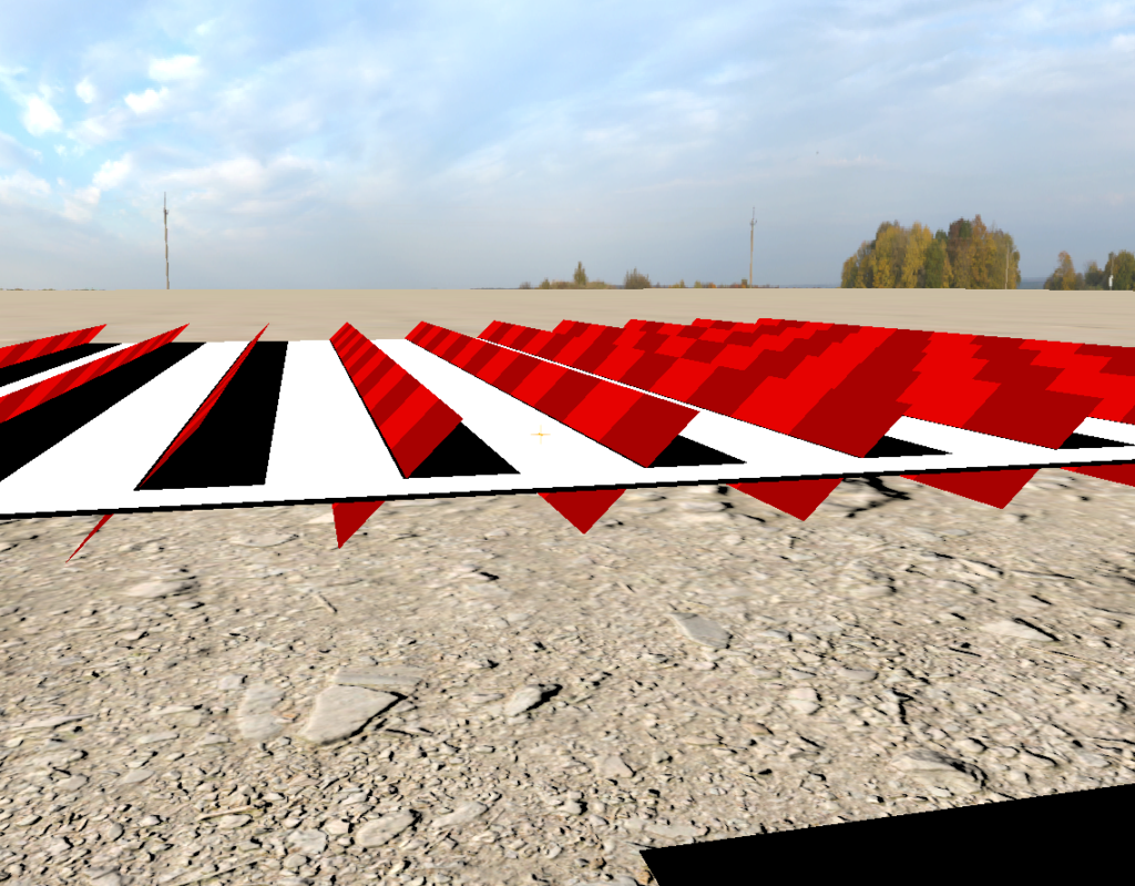
This is much clearer now! The texels are half way through the surface and stick out above it. As the shadowmap resolution is so low, the edge of the surface is not covered by any texels (the center line of those texels hit the floor instead, so the white surface didn’t rasterize into the shadowmap on those locations). The pixels ‘under’ the texels are in shadow and the pixels ‘above’ are not, giving us this alternating shadow pattern.
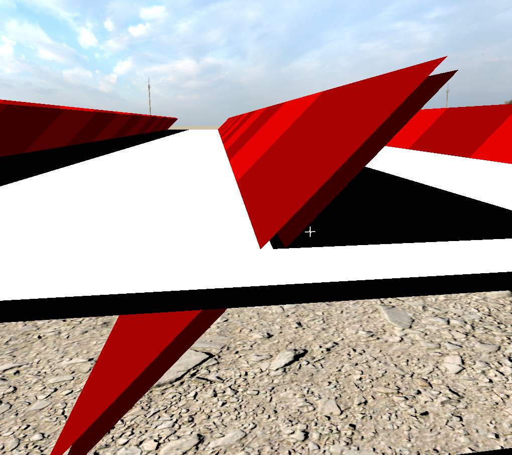
But wait…what’s this?

Why are getting shadows ‘outside’ the shadow texel? We should get shadows under the texel and no shadows above.
The code that produces this shadow is quite sraightforward:
shadowmapCoords = mul(positionWorld, shadowWorldToUV);
lightIntensity *= g_shadowAtlas.SampleCmpLevelZero(g_PointCmpSampler, shadowmapCoords.xy, surfaceZ);
We know the shadowmap is low resolution in terms of its width and height, but how about its (bit) depth? The above images are using a DXGI_FORMAT_D16_UNORM depth format. What happens if we change that to DXGI_FORMAT_D32_FLOAT?

Hey presto! It’s gone! But all that proves is that it’s a depth precision issue. OK, let’s go back to D16 and dig some more.
If this is a precision issue one thing that would be useful would be to visualize the shadowmap precision. The vertex shader for the debug texel quads simply reads the shadowmap and therefore gets a depth value that has been quantized according to the shadowmap format. We can render an additional layer of texels that is pushed one U16N increment further down along the light direction.

When we render geometry into the shadowmap the GPU will have calculated a high precision depth value for each pixel, which gets quantized when stored into the shadowmap. Depending on how the GPU does the float→uint conversion the stored depth must be one of those two red quads.
In our case though we see that the error happens outside of those uppper/lower bounds. Maybe the problem is not the value stored in the shadowmap, but rather the value we’re comparing against. The code doesn’t do anything special, we’re just pushing the world space position through an orthographic projection matrix and taking the Z coordinate, which is in the same [0,1] range as the shadowmap.
shadowmapCoords = mul(positionWorld, shadowWorldToUV);
float surfaceZ = shadowmapCoords.z;
lightIntensity *= g_shadowAtlas.SampleCmpLevelZero(g_PointCmpSampler, shadowmapCoords.xy, surfaceZ);
Let’s try doing the comparison ourselves instead of using a Comparison sampler & instruction.
float surfaceZ = shadowmapCoords.z;
lightIntensity *= surfaceZ < g_shadowAtlas.SampleLevel(g_PointSamplerState, shadowmapCoords.xy).r;

Very interesting, the extra bit of shadow is gone! Given that we didn’t make any changes on how we compute surfaceZ, the difference must be in the use of the comparison sampler. I should note that at this point I checked that g_PointCmpSampler had indeed been setup correctly and was doing a LESS comparison, like the manual comparison above.
SampleCmp should fetch the value from the texture, compare it to the surfaceZ we supplied and return 0 or 1 accordingly. Instictively I was expecting the comparison to be done in floating point….but what if it’s not? What if the GPU converts the supplied surfaceZ to the texture format and compare that value against the fetched value? Can we try simulate that in the manual check?
D3D has some detailed documention on how implementations are expecting to convert from one number format to another. In this case we’re converting surfaceZ from floating point to UNORM, which is covered section 3.2.3.6 of the DX11 functional specification:
- Convert from float scale to integer scale: c = c * (2n-1).
- Convert to integer:
- c = c + 0.5f
- Drop the decimal fraction, and the remaining floating point (integral) value is converted directly to an integer
So it’s basically doing a round()! Let’s try it:
float surfaceZ = round(shadowmapCoords.z * 65535) / 65535;
lightIntensity *= surfaceZ < g_shadowAtlas.SampleLevel(g_PointSamplerState, shadowmapCoords.xy).r;

Aha! There it is! So SampleCmp must indeed be convering the supplied comparison value to the texture format and doing the comparison there. But why does that matter?

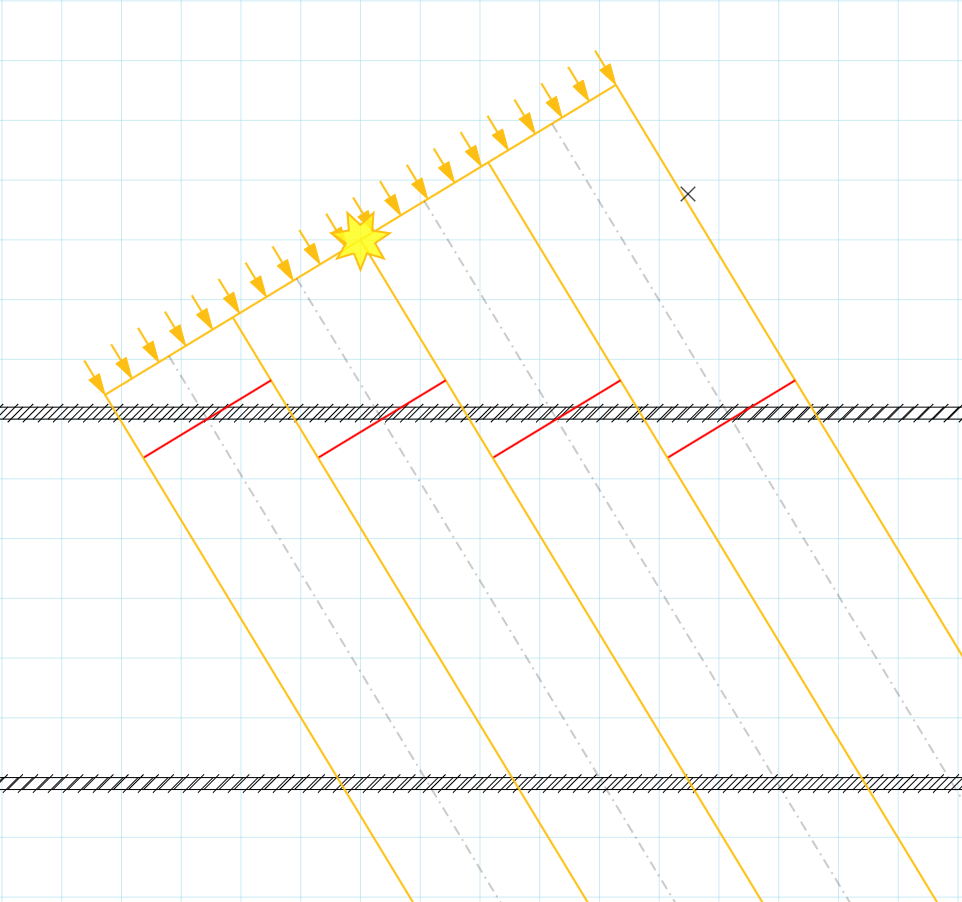
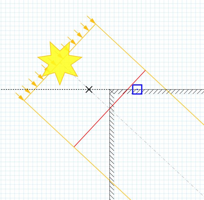
The diagram above shows a single shadow texel. The red line is the depth at the point where the center line of the texel intersects the geometry. If we had infinite precision that’s the value we’d be able to store on the shadowmap. As we’re using U16N format though it gets rounded to the nearest integer, landing on the blue line. In fact any value between the dashed lines will land on the blue line. This is what happens to the pixels on the ‘outside’ of the shadow texels.
Take the green point in the diagram as an example. It has a depth value that is less than the blue line, so it shouldn’t be in shadow. After rounding however it snaps to the same value as the blue line, so the LESS comparison fails, marking the pixel as ‘in shadow’. As a quick test let’s change the comparison to LESS_EQUAL and see if that fixes it:
float surfaceZ = round(shadowmapCoords.z * 65535) / 65535;
lightIntensity *= surfaceZ <= g_shadowAtlas.SampleLevel(g_PointSamplerState, shadowmapCoords.xy).r;
Ah, well, of course, now we have the opposite problem. The pixels just under the texel are rounded down and now end up as ‘not in shadow’. That’s no good. It seems that doing a round() is not a good choice here because it lets values move in both directions. Let’s try doing a floor() instead (and change the comparison back to LESS).
float surfaceZ = floor(shadowmapCoords.z * 65535) / 65535;
lightIntensity *= surfaceZ < g_shadowAtlas.SampleLevel(g_PointSamplerState, shadowmapCoords.xy).r; 
That’s it, that looks correct now. And just for reference, let’s try it with the comparison sampler as well:
float surfaceZ = floor(shadowmapCoords.z * 65535) / 65535;
lightIntensity *= g_shadowAtlas.SampleCmpLevelZero(g_PointCmpSampler, shadowmapCoords.xy, surfaceZ);

Yup, also correct. Calling floor() on the surfaceZ makes it a multiple of a U16N increment so the rounding that SampleCmp will do will have no effect. floor() gives correct results because it’s pulling values in one direction and we can plan for it. ceil() would also work, but we’d need to change the comparison to LESS_EQUAL.
One more thing to note. The conversion from FLOAT to UNORM involves a round(). However note section 3.2.2 of the DX11 spec which says that when converting from a higher range representation to a lower range representation then “round-to-zero” must be used. So if, for example, we had a FP16 format then the conversion from FP32 would be equivalent to the floor() above in the sense that the values will move in a single direction, towards zero.
[TODO] Spot vs Directional
[TODO] Shadows from front faces
[TODO] Camera depth precision?
Receiver Plane Depth Bias
Having dealt with the tiny little overshadowing artifact, we still need to deal with the fact that the shadow texels are protruding outside the surface of the object and causing massive self-shadowing issues.
Let’s review this issue on the 2D diargam:

The red line is the depth value we’re storing in the shadowmap and we have two pixels, red and blue, either side of it. The red pixel is closer to the light and has a depth value less than the shadowmap and is therefore not in shadow. The blue pixel is the opposite, it has a depth value greater than the shadowmap and is therefore in shadow. Given how wide this texel is, there will be lots of pixels that go wrong.
The issue is that the texel stores just a single depth value that is used with pixels throughout the span of that texel. But since we only have that one piece of flat geometry, that single depth value must only be correct at the center of the texel. If we had a higher resolution shadowmap that same region of space would be covered by multiple texels and therefore we’d have more localised depth values to compare against.

In other words, the further away the pixel is from the center of the shadowmap texel, the more inaccurate the comparison will be.
Increasing the resolution of the shadowmap will improve the situation but it won’t make this artifact go away. There are a few approaches to dealing with this issue, but one that I find quite principled is to assume that the shadow receiving surface is planar within the extents of the shadow texel.
Let’s review the geometry in 2D:

We have the receiving surface, which we assume to be flat, with a surface normal N. The aim here is to avoid self-shadowing artifacts, so we need to know if the depth value stored in the shadowmap came from this or some other surface. To help us determine that we can calculate the depth value of the surface at the point where it intersects the texel centerline. If the shadowmap value matches this extrapolated surface depth value then we can mark the pixel as not in shadow.
This is not a new technique, it’s been referenced in a few places such as:
- https://gdcvault.com/play/1013442/Shadow-Mapping-Tricks-and
- https://therealmjp.github.io/posts/shadow-maps/#biasing
- https://www.ludicon.com/castano/blog/articles/shadow-mapping-summary-part-1/
From the diagram above we can see that given the surface normal, N, we can work out a tangent vector, T, which we can break down into two (in 2D) components, Tx along the width of the texel, and Tz along the direction of the light. So if we were to ‘slide’ along the surface from the blue pixel to the center of the texel, we’d be moving by δx on the x axis and δz on the Z axis. This δz is the value we need to add to surfaceZ in the shader to calculate the depth of the surface at the center of the texel. δx is the distance of the pixel from the center of the texel in shadow (UV) space.
We can do this calculation geometrically using vectors, cross products, etc but it gets a bit lengthy in shader code and there’s actually a simpler solution (with some caveats). What we’re actually after is to answer ‘how much does Z change for a small step in UV?’. Well….that’s a derivative. We’re trying to find dZ/dUV.
GPUs provide us with a convenient way of calculating screen-space derivatives, via the ddx/ddy instructions, but we need a derivative in shadowmap UV space. Thankfully we have the chain rule to help us, which states that:
`dz/(dUV) = dz/(dXY)*(dXY)/(dUV)`
where:
- z: depth is shadow space
- UV: texture coordinates in shadow space
- XY: screen coordinates in pixels
Expanding this using partial derivatives we get:
`[[(delz)/(delU)], [(delz)/(delU)]] = [[(delX)/(delU), (delY)/(delU)],[(delX)/(delV), (delY)/(delV)]]*[[(delz)/(delX)], [(delz)/(delY)]]`
Getting the derivative w.r.t. screen coords is easy, we just call ddx/ddy, but how do we get `(dXY)/(dUV)`? The answer is, we don’t. We calculate `(dUV)/(dXY)` and invert the matrix! Calculating the gradient of UV w.r.t. XY is again easily done via ddx/ddy. So updating the above equation, we have:
`[[(delz)/(delU)], [(delz)/(delU)]] = [[(delU)/(delX), (delV)/(delX)],[(delU)/(delY), (delV)/(delY)]]^-1*[[(delz)/(delX)], [(delz)/(delY)]]`
Inverting a 2×2 matrix is straightforward:
`[[a, b],[c, d]]^-1 = |[a, b],[c, d]|*[[d, -b],[-c, a]]=1/(a*b-c*d)*[[d, -b],[-c, a]]`
Applying this makes our equation as follows:
`[[(delz)/(delU)], [(delz)/(delU)]] = 1/((delU)/(delX)*(delV)/(delY)-(delV)/(delX)*(delU)/(delY))*[[(delV)/(delY), -(delV)/(delX)],[-(delU)/(delY), (delU)/(delX)]]*[[(delz)/(delX)], [(delz)/(delY)]]`
Turning this into shader code:
float3 shadowmapCoords = mul(positionWorld, shadowWorldToUV).xyz;

float2 dU_dXY = float2( ddx_fine(shadowmapCoords.x), ddy_fine(shadowmapCoords.x) );
float2 dV_dXY = float2( ddx_fine(shadowmapCoords.y), ddy_fine(shadowmapCoords.y) );
float2 dz_dXY = float2( ddx_fine(shadowmapCoords.z), ddy_fine(shadowmapCoords.z) );

float detJ = dU_dXY.x * dV_dXY.y - dV_dXY.x * dU_dXY.y;

float2 dz_dUV = 0;

if (detJ != 0)
{
    dz_dUV.x = dot( float2( dV_dXY.y, -dV_dXY.x), dz_dXY) * rcp(detJ);
    dz_dUV.y = dot( float2(-dU_dXY.y,  dU_dXY.x), dz_dXY) * rcp(detJ);
}
And then using this to calculate the bias:
float2 distanceToTexelCenterUV = 0.5 - frac(shadowmapCoords.xy * kShadowmapSize);
distanceToTexelCenterUV *= rcp(kShadowmapSize);

float slopeBias = dot(distanceToTexelCenterUV, dz_dUV);

shadowmapCoords.z += slopeBias;

float surfaceZ = floor(shadowmapCoords.z * 65535) / 65535;

lightIntensity *= g_shadowAtlas.SampleCmpLevelZero(g_PointCmpSampler, shadowmapCoords.xy, surfaceZ);
Which then gives us correct shadows:

What if the det is zero?
Ship it?
Not so fast! There are a few problems to be aware of.
First off, we’ve made an assumption that the surface is flat across the entire span of the shadow texel, but as shown on the diagram below that’s not always going to be true. The blue pixel will calculate a bias shown at the ✕ point but the shadowmap stores the depth of the vertical surface. In fairness, this is a complex case and it would be difficult to get a robust solution.
A similar setup would be the one shown below, which breaks the ‘across the entire span of the texel’ assumption. It also demonstrates that the slope bias in this case would cause the pixel to be in shadow when it wouldn’t have been originally, had we not applied the bias. It’s probably reasonable to assume that the slope bias should only be used to move things out of shadow, by clamping it to zero, i.e.
// Note: if you're doing reverse z it would be max(0, ...)
float slopeBias = min(0, dot(distanceToTexelCenterUV, surfaceSlope_dz_dUV));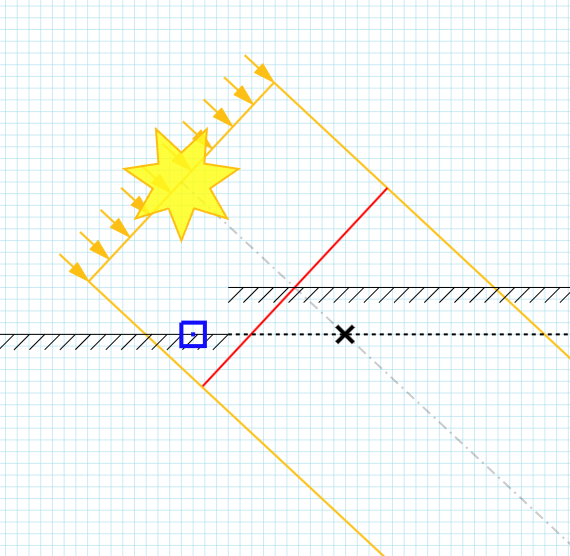
Another common problem stems from the use of ddx/ddy. Doing the derivatives in screenspace assumes that the surface is flat across the 2×2 pixel block being shaded and, more importantly, that all pixels in the 2×2 block belong to the same surface. This is the same kind of issues you’d get when reconstructing a surface normal by taking the screenspace derivatives of the position. Any discontinuities in the screen data, such as at the boundaries of objects for example, will result in very wrong results. There is no real fix for this. Clamping the bias will help a bit but there will always be pixel-level artifacts. If you have a way of sourcing the surface normal, e.g. by doing forward shading, visibility buffer shading or explicitely storing it in a g-buffer, then computing the UVW slope geometrically would be better as you’d avoid any ddx/ddy issues.
Applications
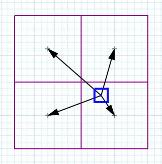
So far we’ve looked at the deviation of the pixel from the texel center. This assumes a point sampling scenario where a pixel would projected into shadowmap space and we’ll sample the texel that it lands on. How about when doing bilinear filtering? After all, that was the original PCF application back in the PS3 days!
In 2×2 PCF we’d do a bilinear filter of the depth comparison result, so for each pixel we’d sample 4 texels, compare their depths to the pixel depth, produce 4 [0|1] values and blend them using the standard bilinear filtering weights. The code is very simple:
lightIntensity *= g_shadowAtlas.SampleCmpLevelZero(g_BilinearCmpSamplerState, shadowmapCoords.xy, surfaceZ);The problem is that we’re comparing 4 texel depths against just the one pixel depth, i.e. the comparison value is the same for all 4 texels. We already saw that even in the point sampling case not accounting for the distance between the pixel and the texel center leads to significant artifacts. Now we’re straying even further afield, onto neighboring texels so the error would be even worse!

And indeed it is. In the image above a slope bias has been calculated in the same way as before for the primary pixel but it doesn’t help with the other 3 texels. Alas, SampleCmp() only takes a scalar comparison value. It would have been really useful if we could supply a float4 so that we can supply a different comparison value for each of the 2×2 texels.
If we can’t use SampleCmp, then the next best thing we can do is call Gather() to fetch the four texel values and then do the comparion ourselves. This will allow us to calculate 4 different slope bias values, from the 4 distances of the pixel to the center of each of the texels.
// Note: adding 1/512 to make sure frac() and gather() work on the same set of texels
// See: https://www.reedbeta.com/blog/texture-gathers-and-coordinate-precision/
float2 fracCoords = frac(shadowmapCoords.xy * kShadowmapSize - 0.5 + 1.0/512.0);

float4 shadowDepths = g_shadowAtlas.Gather(g_BilinearSamplerState, shadowmapCoords.xy);

// https://learn.microsoft.com/en-us/windows/win32/direct3dhlsl/gather4--sm4-1---asm-
// The four samples that would contribute to filtering are placed into xyzw in counter clockwise order starting with the sample to the lower left of the queried location.
// This is the same as point sampling with (u,v) texture coordinate deltas at the following locations: (-,+),(+,+),(+,-),(-,-), where the magnitude of the deltas are always half a texel.
float2 offsets[4] = { {-1,1}, {1,1}, {1,-1}, {-1,-1} };

float4 surfaceZ = 0;
surfaceZ[0] += min(0, dot(offsets[0] * rcp(kShadowmapSize) * float2(  fracCoords.x, 1-fracCoords.y), dz_dUV));
surfaceZ[1] += min(0, dot(offsets[1] * rcp(kShadowmapSize) * float2(1-fracCoords.x, 1-fracCoords.y), dz_dUV));
surfaceZ[2] += min(0, dot(offsets[2] * rcp(kShadowmapSize) * float2(1-fracCoords.x,   fracCoords.y), dz_dUV));
surfaceZ[3] += min(0, dot(offsets[3] * rcp(kShadowmapSize) * float2(  fracCoords.x,   fracCoords.y), dz_dUV));

surfaceZ += shadowmapCoords.z;

float4 attenuation4 = surfaceZ < shadowDepths;

float attenuation = lerp( lerp(attenuation4[3], attenuation4[2], fracCoords.x), lerp(attenuation4[0], attenuation4[1], fracCoords.x), fracCoords.y );

discreteLight.attenutation *= attenuation;
(hat tip to @Reedbeta for this article explaining why we need a small bias on frac!)
With the correct bias values applied we get correct bilinearly filtered shadows.

The same principle applies in other situations where we sample ‘away from the center’, a very common example being when doing soft shadows where we might make shadow samples within a radius of a center tap (which is where the pixel is).
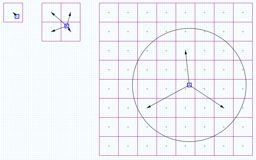
Just like before we’ll need to assume that the surface is flat and continuous across the entire area being sampled and if that holds true then we can just calculate the distance from the pixel to each tap and multiply by dz/dUV like before.
Alternatives to Receiver Plane Depth Bias
As we’ve seen the receiver plane bias is not a perfect solution and does add a few instructions to the shader. There are a few alternatives that people use but the the two that seem quite common are: biasing along the surface normal and slope bias using the rasterizer state.
Biasing along the surface normal involves ‘growing’ the surface, sort of blowing it up a little like a baloon! It’s an intuitive solution to the self-shadowing problem. At the point where we’re about to sample the shadowmap, we apply a bias to the position along the normal and then project to shadowmap space and carry on as usual. Since the receiving surface is ‘larger’ than the shadow casting one, the chances of self-shadowing are reduced. The problem with this approach is that there is no perfect amount by which we need to bias by. It’s typically exposed as a setting that needs to be tweaked per light or per shot.
The other approach is to utilize the depth bias features exposed via the Rasterizer state. There are two bias method exposed: a constant bias and a slope based bias. These have been available since early DX9 days and the latter was very likely added specifically to help with shadowmaps. These biases would typically be applied when rendering geometry into the shadowmap, which means that we need to bias in the opposite direction as what we saw above. Instead of trying to pull the receiving geometry up towards the light, here we’re trying to push the shadow casting geometry down, away from the light. Either way the aim is to add a small gap between the caster and the receiver.
The constant bias is just a scalar value that’s added to the value stored in the depth buffer. Similar to the normal bias it doesn’t have a perfect value. You’d typically add one or more multiples of the smallest representable increment of the depth buffer format and then increase it as necessary. If you add too much, you get a gap (light leak) in your shadows. It’s not a great approach.
The slope based depth bias seems much more useful. Here the GPU will compute the slope of the surface being rasterized and you can supply a value that will be multiplied by that slope and the result added to the depth for that pixel. That sounds exactly like we’ve been doing in the shader! It sounds perfect!
Sadly, it’s not. The main issue is that we need to supply a single (scalar) value that will be multiplied by the slope. From the discussion above that value would need to be the distance between the pixel being shaded and the texel center….but each pixel has a different distance to the texel center it would sample! So a single value won’t be correct. You could supply the maximum distance between a pixel and the texel center maybe…for example half a texel width. It would be an overestimate so it might lead to some shadow separation. For 2×2 PCF and large kernel soft shadows things get more complicated further. Supplying the maximum distance becomes even more wrong there.
The other issue is with the slope calculation. Both Vulkan and D3D compute the slope as
MaxDepthSlope = max( abs(dz/dX), abs(dz/dY) )
(X and Y here are equivalent to U and V earlier as this bias is applied when rendering into the shadowmap)
As we saw earlier we would ideally take both the X and Y slopes into account separately and would also honor their sign. Doing a max() and an abs() will lead to another overestimation. It’s understandable from an API point of view, but makes this feature more awkward to use and will again require lots of tweaking to get correct results.
DX11 Functional spec – Depth Bias
Camera Depth Bias
Useful Links
- https://therealmjp.github.io/posts/shadow-maps/
- https://gdcvault.com/play/1013442/Shadow-Mapping-Tricks-and
- https://microsoft.github.io/DirectX-Specs/d3d/archive/D3D11_3_FunctionalSpec.htm#15.10%20Depth%20Bias
- https://registry.khronos.org/vulkan/specs/latest/html/vkspec.html#primsrast-depthbias-computation